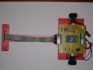
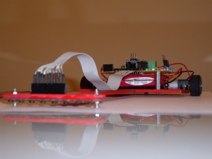
Tenía pendiente publicar el modo en el que había construido mi robot Eva. Este robot hizo el segundo mejor tiempo en la clasificación del cosmobot de 2011 y quedó entre los 8 primeros, desbancado por su hermano VELORP (otro de los robot Zero) en cuartos de final. Básicamente comparte muchas características del robot Zero ya que ha sido también probado en el medialab y se han sacado las mismas conclusiones, sin embargo la placa es distinta y la programación también.
Los componentes que tienen en común son:
- Placa de infrarrojos de Pololu (en este caso la digital)
- Motores 1:10 HP de Pololu
- Baby orangutan de Pololu
- Chasis de forex (PVC expandido o espumado)
Sin embargo las ruedas son las del miniz, ya que logran poner el chasis más pegado al suelo y derrapan menos.
La batería no es una Lipo 1S sino 2S (7,4 V.) enchufada directamente a la baby orangutan. Esta se encuentra entre los motores para dejar el centro de gravedad en medio y centrar más el peso en las ruedas.
Como no tiene conversor DC-DC que mantenga un voltaje continuo hacia los motores, he usado un divisor de tensión que mide el voltaje de la batería y así puede calcular el PWM que tengo que enviar a los motores según esté más o menos cargada la batería. Esto se consigue con la siguiente fórmula:
PWM * 7,4 / batería
- PWM: Es el PWM que queremos enviar al motor.
- 7,4: Es el voltaje normal que tiene una batería de Lipo 2S.
- batería: Es el voltaje que tiene la batería en un momento dado.
Así si le meto 180 de PWM y tengo 8,4 voltios en la batería al final mando al motor 159 de PWM.
Si en el anterior caso en la batería tengo 7,4 voltios entonces da los 180 exactos de PWM.
Si la batería está a 7 voltios le metería al final 190 de PWM.
Como la tensión de la batería no es constante sino que tiene picos, es mejor tener 10 valores de tensión y luego calcular la media arimética para tener un valor más coherente.
El divisor de tensión también es útil para saber cuando la batería está cerca de agotarse y parar el robot, salvando así que las celdas pasen por debajo de los 3 voltios.
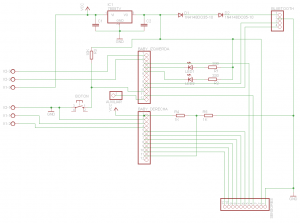
Este es el esquema de la placa:
A comentar:
- Tiene un pin auxiliar por si fuese necesario usarlo para algo.
- Tiene unos pines para añadirle un módulo bluetooth (se baja la tensión con un par de diodos para lograr 3,6 V.).
- Usa un 7805 para alimentar los sensores y el bluetooth.
El código fuente que he desarrollado lo expongo a continuación. Este implementa el control Proporcional Derivativo y hace uso de las librerías que provee Pololu para poder manejarse con los sensores y con la baby orangutan.
velocistaB_2.h
|
1 2 3 4 5 6 7 8 9 10 11 12 13 |
#define KP 0.12 #define KD 0.36 #define PWM_PUNTA 180 #define PWM_CALIBRA 50 int max(int valor1, int valor2); int min(int valor1, int valor2); void alarma(); int mili_voltios(); void inicializa(); void calibra(); void movimiento(); void parada(); |
velocistaB_2.c
|
1 2 3 4 5 6 7 8 9 10 11 12 13 14 15 16 17 18 19 20 21 22 23 24 25 26 27 28 29 30 31 32 33 34 35 36 37 38 39 40 41 42 43 44 45 46 47 48 49 50 51 52 53 54 55 56 57 58 59 60 61 62 63 64 65 66 67 68 69 70 71 72 73 74 75 76 77 78 79 80 81 82 83 84 85 86 87 88 89 90 91 92 93 94 95 96 97 98 99 100 101 102 103 104 105 106 107 108 109 110 111 112 113 114 115 116 117 118 119 120 121 122 123 124 125 126 127 128 129 130 131 132 133 134 135 136 137 138 139 140 141 142 143 144 145 146 147 148 149 150 151 152 153 154 155 156 157 158 159 160 161 162 163 164 165 166 167 168 169 170 171 172 173 174 175 176 177 178 179 180 181 182 183 184 185 186 187 188 189 190 191 192 193 194 195 196 197 198 199 200 201 202 203 204 205 206 207 208 209 210 211 212 213 214 215 216 217 218 219 220 221 222 223 224 225 226 227 228 229 230 231 232 233 234 235 236 237 238 239 240 241 242 243 244 245 246 247 248 249 250 251 252 253 254 255 256 257 258 259 260 261 262 263 264 265 266 267 268 269 270 271 272 273 274 275 276 277 278 279 280 281 282 283 284 285 286 287 288 289 290 291 |
#define F_CPU 20000000UL #include <avr/io.h> #include <avr/eeprom.h> #include <stdint.h> #include <avr/interrupt.h> #include <util/delay.h> #include <stdio.h> #include <string.h> #include <pololu/orangutan.h> #include "velocistaB_2.h" volatile int8_t boton; ////////////////////////////////////////////////////////////////////////////////////////////////////////////////// /* Interrupción que salta cuando se pulsa el botón */ ISR(INT0_vect) { if(boton == 0) // se pulsa para calibrar { boton = 1; } else if(boton == 2) // se pulsa para moverse { boton = 3; } else if(boton == 5) // se pulsa para pararse { boton = 6; } } ////////////////////////////////////////////////////////////////////////////////////////////////////////////////// /* Devuelve el valor máximo */ int max(int valor1, int valor2) { if(valor1 > valor2) { return valor1; } else { return valor2; } } ////////////////////////////////////////////////////////////////////////////////////////////////////////////////// /* Devuelve el valor mínimo */ int min(int valor1, int valor2) { if(valor1 < valor2) { return valor1; } else { return valor2; } } ////////////////////////////////////////////////////////////////////////////////////////////////////////////////// /* Enciende y apaga los leds repetitivamente */ void alarma() { uint16_t indice; for(indice = 0; indice < 10; indice++) { PORTB &= ~((1 << PB1) | (1 << PB2)); delay_ms(200); PORTB |= (1 << PB1) | (1 << PB2); delay_ms(200); } } ////////////////////////////////////////////////////////////////////////////////////////////////////////////////// /* lee la carga de la batería a través del divisor de tensión */ int mili_voltios() { uint16_t indice; long suma = 0; static uint16_t medidas[] = {3700,3700,3700,3700,3700,3700,3700,3700,3700,3700}; if(analog_is_converting() != 0) { return -1; } for(indice = 0; indice < 9; indice++) { medidas[indice + 1] = medidas[indice]; } medidas[0] = to_millivolts(analog_conversion_result()); for(indice = 0; indice < 10; indice++) { suma += medidas[indice]; } start_analog_conversion(6); return suma / 10; } ////////////////////////////////////////////////////////////////////////////////////////////////////////////////// /* Inicializamos todos los parámetros */ void inicializa() { uint16_t *maximos; uint16_t *minimos; unsigned char qtr_rc_pins[] = {IO_D4, IO_B0, IO_C5, IO_C4, IO_C3, IO_C2, IO_C1, IO_C0}; DDRB |= (1 << PB1) | (1 << PB2) | (1 << PD7); MCUCR |= (1<<ISC01) | (1<<ISC00); EIMSK |= (1 << INT0); sei(); set_analog_mode(MODE_8_BIT); start_analog_conversion(6); serial_set_baud_rate(9600); // Comprueba si hay valores guardados en la EEPROM para hacer o no la calibración qtr_rc_init(qtr_rc_pins, 8, 5000, 255); if(eeprom_read_byte(0) != 0) { qtr_calibrate(QTR_EMITTERS_ON); maximos = qtr_calibrated_maximum_on(); minimos = qtr_calibrated_minimum_on(); eeprom_read_block (maximos, (const void *)0, 16); eeprom_read_block (minimos, (const void *)16, 16); PORTB |= (1 << PB1) | (1 << PB2); boton = 2; } else { PORTB &= ~((1 << PB1) | (1 << PB2)); boton = 0; } } ////////////////////////////////////////////////////////////////////////////////////////////////////////////////// /* Proceso de calibración de los sensores y guardado de los valores en la EEPROM */ void calibra() { uint16_t indice; int16_t mvoltios; uint16_t *maximos; uint16_t *minimos; for (indice = 0; indice < 10; indice++) { mvoltios = mili_voltios(); } if(mvoltios != -1 && mvoltios < 3100) // Batería con menos de 3,1 v (en realidad menos de 6.2 v.) { alarma(); boton = 0; return; } set_m1_speed(-PWM_CALIBRA); set_m2_speed(PWM_CALIBRA); for (indice = 0; indice < 250; indice++) { qtr_calibrate(QTR_EMITTERS_ON); delay(20); } set_m1_speed(0); set_m2_speed(0); maximos = qtr_calibrated_maximum_on(); minimos = qtr_calibrated_minimum_on(); eeprom_write_block (maximos, (void *)0, 16); eeprom_write_block (minimos, (void *)16, 16); boton = 2; } ////////////////////////////////////////////////////////////////////////////////////////////////////////////////// /* El robot empieza a moverse y calculamos el PD */ void movimiento() { unsigned int sensores[8]; int posicion; float cantidad_error; static float anterior_error = 0; int pid; int mvoltios; float mvoltios2; int pwm1; int pwm2; mvoltios = mili_voltios(); if(mvoltios != -1 && mvoltios < 3100) // Batería con menos de 3,1 v (en realidad menos de 6,2 v.) { parada(); alarma(); return; } if(get_ms() >= 1000) // pasado 1 segundo ya no hay rebotes y se permite pulsar el botón de nuevo para parar el robot { boton = 5; } posicion = qtr_read_line(sensores, QTR_EMITTERS_ON); cantidad_error = 3500 - posicion; pid = cantidad_error * KP; pid += (cantidad_error - anterior_error) * KD; anterior_error = cantidad_error; pwm1 = PWM_PUNTA; pwm2 = PWM_PUNTA; // hacia la izquierda if(pid > 0) { pwm1 -= pid; PORTB &= ~(1 << PB2); PORTB |= (1 << PB1); } //hacia la derecha else if(pid < 0) { pwm2 += pid; PORTB &= ~(1 << PB1); PORTB |= (1 << PB2); } // centrado else { PORTB &= ~((1 << PB1) | (1 << PB2)); } // Ajustamos el PWM según la carga de la batería mvoltios2 = mvoltios / 1000; pwm1 = (float)pwm1 * 3.7 / mvoltios2; pwm2 = (float)pwm2 * 3.7 / mvoltios2; pwm1 = max(min(pwm1, 255), 0); pwm2 = max(min(pwm2, 255), 0); set_m1_speed(pwm1); set_m2_speed(pwm2); delay_ms(2); PORTD ^= (1 << PD7); //para comprobar la frecuencia } ////////////////////////////////////////////////////////////////////////////////////////////////////////////////// /* Se para el motor */ void parada() { set_m1_speed(0); set_m2_speed(0); PORTB |= (1 << PB1) | (1 << PB2); delay_ms(1000); boton = 2; } ////////////////////////////////////////////////////////////////////////////////////////////////////////////////// int main(void) { inicializa(); while(1) { if(boton == 1) { calibra(); } else if(boton == 3) { boton = 4; time_reset(); } else if(boton == 4 || boton == 5) { movimiento(); } else if (boton == 6) { parada(); } } return 0; } |
Como habeis podido leer en el código fuente tiene un sistema de calibrado por el cual guarda en la EEPROM los valores minimos y máximos de los sensores la primera vez que se calibra y ya no es necesario hacerlo en futuras ocasiones a no ser que cambien las condiciones de iluminación.
La calibración consiste en dejar el robot en la pista, pulsar el botón y que de unas vueltas sobre sí mismo, lea los valores de blanco y negro y los guarde además en la EEPROM. Las siguientes veces que pulsemos el botón ya no se hará la calibración y empezará a correr el robot.
Para realizar la calibración la EEPROM debe estar vacía, y eso se consigue con el siguiente programa:
|
1 2 3 4 5 6 7 8 9 10 11 12 13 14 15 16 17 18 19 20 21 22 23 24 |
#include <avr/eeprom.h> int main(void) { uint8_t ceros[32]; uint16_t indice; DDRB |= (1 << PB1) | (1 << PB2); for(indice = 0; indice < 32; indice++) { ceros[indice] = 0; } eeprom_write_block (ceros, (void *)0, 32); if(eeprom_read_byte(0) != 0) { PORTB |= (1 << PB1) | (1 << PB2); } for(;;); return 0; } |
Y por último un video (gracias Puck2099) de cómo funcionó en la cosmobot (tuve que bajarle un poco el PWM porque al final derrapa un poco y cambia de sentido):


Oscar,
Enhorabuena, aunque ya te felicité allí in-situ, por tu gran trabajo y tus buenos resultados. Y por ser un tío tan majo.
Espero que en la edición del año que viene nos podamos ver ya con un velocista.
Un saludo.
Gracias.
Cuando tengas ese velocista comentanos qué tal y si un día quieres pasarte por el medialab ya sabes donde está 😉
Muchas gracias por publicar todas las especificaciones y código del robot, y enhorabuena por los resultados en Cosmobot.
La verdad es que la competición estuvo muy entretenida, sobre todo a partir de cuartos. Felicidades!
No hay de qué por lo del video, Óscar, ahora le cambio la descripción con el nombre de tu robot 🙂
makefile file is missing 🙁
There are a few operating sytems and compilators for avr that use different make files format, so with source code and know how to compile it in your platform should be enough.
Hey, Oscar! I really liked your robot! I want to do such a thing, too! Unfortunately, I have weeded from the controller, I collect myself and the controllers want to use a 16 Mhz atmega8. I have a motor controller is the same! Can I use your code on a different microprocessor, if I change the pins, I do not use Arduino IDE, but I write under the winavr. It’s very interesting to know the answer. And here’s another. You’re not using PWM code for motor control?
I think you can use an atmega8, however you have to use the same connections as if it were a baby orangutan controller. The code above is compiled with winavr using the pololu library, so the PWM is set by the function set_mX_speed where X is 1 or 2.
Many thanks, Oscar!
Could you explain me this.
You use the INT0 interrupt. And it’s kind of interruption for the buttons, then there should be a button each time the robot to work?
Yes
To start the race you have to push the button when the arbiter says: GO!
And yet, you do not know if there is a site for a mini-sumo or kegelringa
Hey, Oscar! I came a couple of questions about your code, I understand its just a style of writing I do not know, please tell me all the questions.
a) Where did you initialize the button on the input and how it relates to the variable boton.
b) Why should you have an array of medidas[]
a) By default all pins in atmega are input at beginning, so for the button I only have to activate the interrupt: EIMSK |= (1 << INT0); and sei(); b) An arithmetic mean to get the battery state.
«Como no tiene conversor DC-DC que mantenga un voltaje continuo hacia los motores, he usado un divisor de tensión que mide el voltaje de la batería y así puede calcular el PWM que tengo que enviar a los motores según esté más o menos cargada la batería. Esto se consigue con la siguiente fórmula:»
Oscar, Tell me please, what is it? We do not use PWM, we just serve on the PWM outputs 5V.
And please tell me where there is a setting in the ADC output code (to get the data from the battery), I just can not use the ADC port 6, and can only be used in your controller, ADC 5.
And say, make sure the battery should be 7.4V, I want to use the battery to 5V.
I don’t understand the phrase «We do not use PWM, we just serve on the PWM outputs 5V» If you don’t use PWM, how do you change the motor speed?
I use the pololu libraries to read the ADC in mili_voltios function.
You can use 5V battery if you want, however you have to do some changes in code: 3700 to 2500 & 3100 to the value from you want to stop the robot when low battery (i.e: 2000).
Hello Oscar!
I decided to build your robot, because have free time)
I collect robot Atmega8 16mzh.
I read the code, and the robot learned that I have issues))
Tell me please, what you specify in the code that you have an 8-bit ADC, the datasheet for megu168 says that there is 10-bit ADC.
Tell me please, to work with the robot should have 7.4V battery?
I have in my mege8 no port PС6, which is used in your controller to exit the STBY in driver motors.
Where can I change this output in the library rololu and then I can not find (((
I would like to exit STBY moved to another port
In function inicializa I change the ADC to 8 bit with set_analog_mode(MODE_8_BIT);
You can use a 5V battery, but you have to do the changes that I have told you in the last comment.
Where did you find the PC6 port? I don’t use it. It is reserved for reset the microncontroller: http://www.pololu.com/docs/0J14/all
Oscar sorry for the ill-defined question, I have a problem with the English language. I was just with Russia.
1) in the scheme RC6 baby orangutan is used to output from the STBY TB6612FNG, or rather to run this chip. If it does not apply a high level of the motor will not run (see scheme).
2)
You can left STBY connected to Vcc with a 10K resistor and forget PC6 🙂
awww, its fantastic…..
i have some questions, later i’ll ask you…………….
Listen to the flash EEPROM, I do not understand how to get the file that will flash it?
To erase the eeprom you have to program the code before the video.